Hard to believe that Part 1 of this series was 10 years ago! To say that many things happened during that time would be an understatement. The pandemic, lockdown, loved ones passing away, and many changes. A few weeks ago, I “found” the unfinished boat tucked away in a shoebox, where I'd put it aside. Its cute size and recent memories of taxiing my plane on water made me want to complete it. This would be my first time building and sailing a radio control boat. This one is based on the Papaya 3 Footy by Mario Stiller. Single chine, flat bottom. Before the delay, I had started to build it in 3mm Depron foam, instead of Stiller's balsa, glued together with Uhu Por. This post documents how I completed the model and tested it ready for the maiden.
Keel and Bulb
I do not fish, but 10y ago I’d also put aside a bag of 200g fishing weights. Small miracle that I found the bag; one of them would be the keel bulb. I found some material for the keel — a piece of knot-free pine. To join the two, I drilled and scraped a slot in the keel bulb, and shaped a tenon in the pine to fit. By this stage, the bulb weighed 185g. Obviously, it would not be sensible to glue it on to the keel wood at this stage because of all the other building work still to do. So I set it safely aside.
With wood glue, interior gunwhales (or ‘gunnels’) were added in balsa at the rear and thin obeche at the front, as it was flexible enough to follow the curve. These increase rigidity and create a gluing area, e.g. for the mast tube support plank and decking. Again a departure from Stiller’s original plan.
Next I cut a slot in the hull bottom for the keel. Very scary to do, but I tried to think very carefully about every step before cutting anything. I used part of the bulkhead as the anchor point for the keel which I cut a step and a slot on to.
While epoxying the keel in position, I also put a fillet around the outside of the slot, just to be sure.
Once it had set, I reinforced the bulkhead with extra balsa timbers, also with epoxy.
The nose piece was another problem. I tried a foam block which looked ugly and was difficult to shape. In the end I simply glued a triangular piece of balsa in the centre and placed blocks on each side of that. Then just carved and sanded it. It came out fine - there are photos of it later on in this blog post.
First-time Float
At this point I decided to give it a float in the sink to check for leaks. A lot of fun, and it was leak-free! Depron sticks well with Uhu Por and the bond lasts well - at least 10y it seems. The epoxy around the keel slot was sound.
Mast and Sails
The pine mast support plank was placed athwart, glued to the inner gunnels.
Underneath the plank on the floor was the mast footing, which was made as a sandwich of balsa, ply, a tiny square of thin stainless steel under a pine block with a hole in it. The steel was from an old floppy disk — the part that slides across to reveal the tape. The metal is necessary to prevent the mast drilling a hole in the bottom of the boat as it spins.

Decided to put the mast tube at 66% of the overall boat length measured from the rear, as my research showed that this was a common place for una rigs and McRigs (more on McRigs below). This is different to Mario Stiller’s design, which shows a full Bermuda-style mainsail and jib. I toyed with the idea of adding further mast tubes and decided against it. Too much hassle, weight and surely I should be able to get at least one sail rig to work with a solo mast position? After playing around with alloy tubing in my stock, I picked a tube diameter that accepted a 3mm carbon tube, which will be the mast for one of my sails. I cut a smaller diameter alloy tube piece to insert into the mast tube. It makes a lining that allows a wire Z shape mast of a McRig to spin beautifully in the mast tube. This gives me at least 2 mast options. I took care to ensure that the bottom of each mast was slightly rounded so that it could spin well on the steel floppy disk piece under the footing.
Then I took a bit of time to make masts and sails and to my surprise found it quite enjoyable. I think they are easier to build than wings and you can be quite creative. A new purchase was an eyelet punch and I had to revise my knots.
It was enjoyable to make bend wire attachments for lines and rigging. Unlike aircraft undercarriage, you’re working with thin wire so bending is easier and you can let creativity flow.
In this post you will see photos of three sails. The blue one is about 65in2 in area.
The white with orange trim is 105in2 and the largest, the McRig style, in white and purple is about 115 in2.
These photos also show the simple stand that I made in a few minutes. You need one! I decided that I will use the white and orange sail first to see if I can get the hang of this RC yachting malarkey.
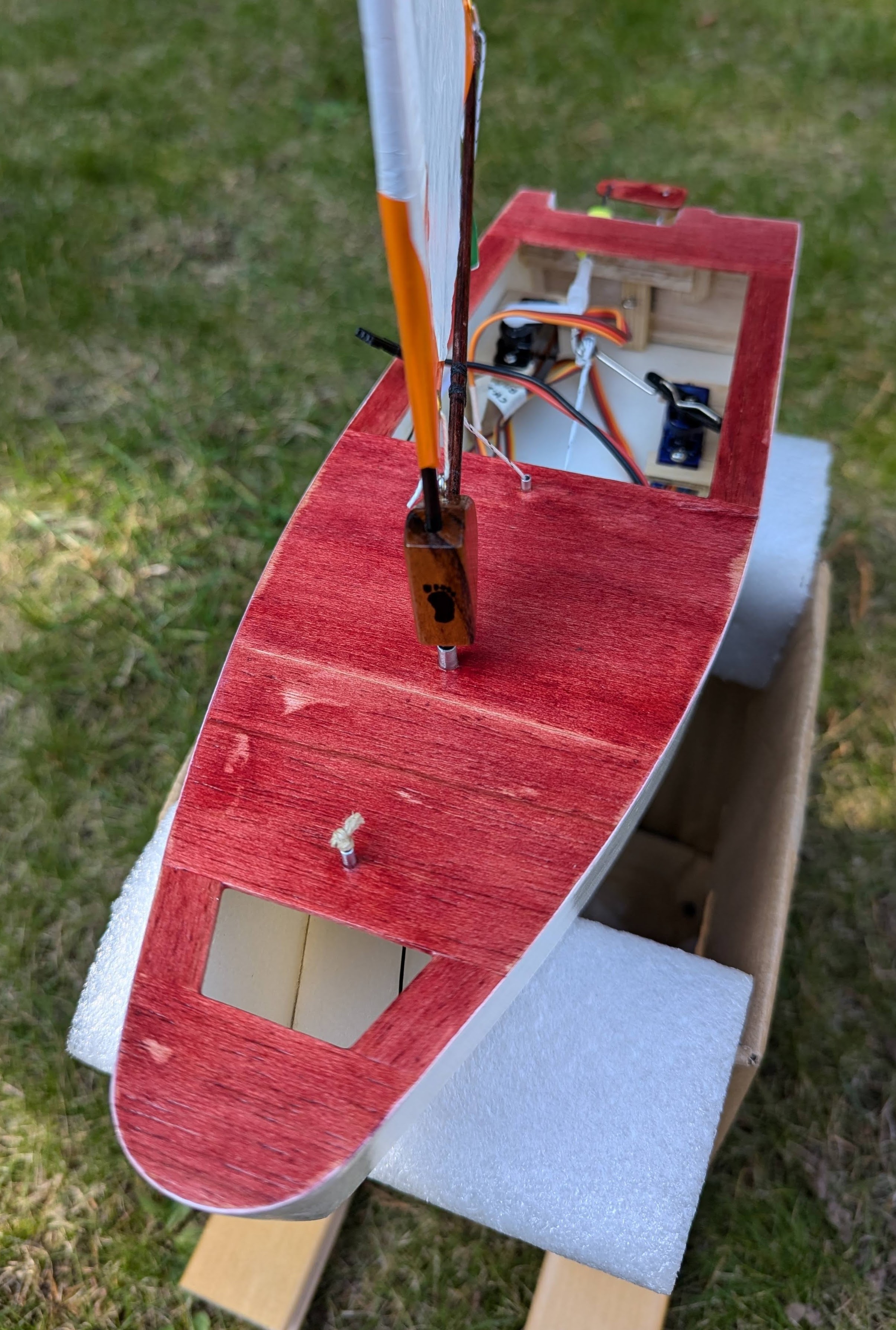
The block attaching the boom to the mast is made of rosewood. Just a piece of scrap that I had lying around and I'm particularly pleased with the little footy logo on its front (photo of that later below). It's probably overbuilt but it does the job.
Rigging, Servo Mounts and Controls
I prepared runs to allow the main sheet to pass through the deck; a short piece of aluminium tube set into a small disc of pine. These would be glued under the decking pieces. As I fitted the decking of 1.5mm balsa, I also glued in the sheet tubes. I tried to put these around 55 mm from the centre of the mast hole because in my tests this is the distance that seemed to work ok.
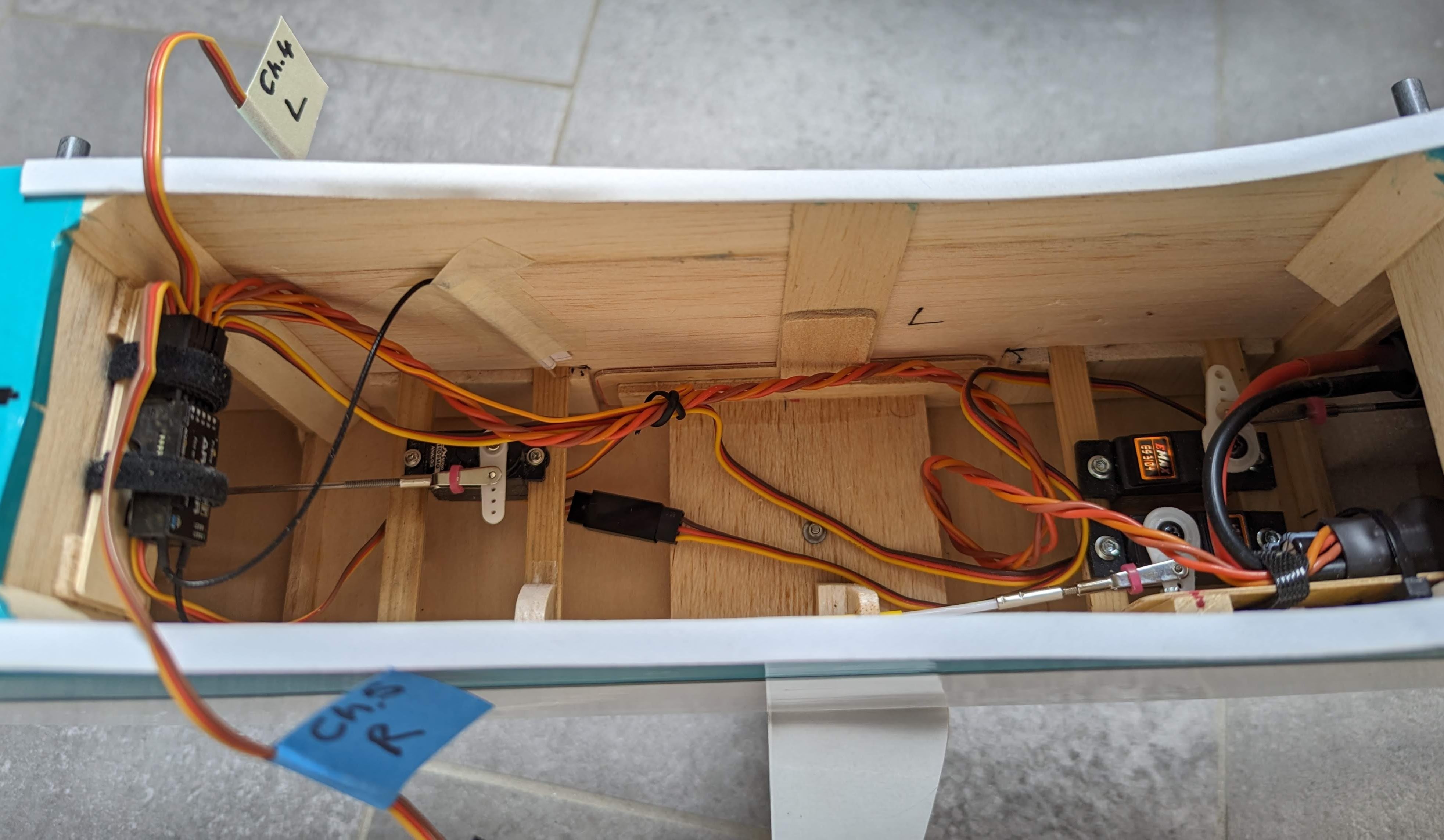
I built the servo mountings as simply as possible - merely a ply u-shaped piece on a balsa block. These were assembled using waterproof white wood glue and then fixed in the boat using UHU Por. The mainsheet servo arm was bent out of a stiff piece of wire that I had lying around.
After umming and ahhing about mounting the battery and the receiver, I opted for the simplest idea, which was velcro that had been a UHU Por-ed in position. The rationale is that the battery being heavy can sit very close to the middle of the boat and hopefully provide the right balance. Antennae held in place with paper tubes, tips horizontal and perpendicular to each other, I did a range check and it was fine.
The rudder that I had started to make in Part 1 seemed flimsy to me because of the flexible carbon tube. On reflection, I opted instead for a good hard piece of balsa attached to a ply control horn, pinned with gussets. The wired hinge would be stiffer under load. The rudder was then glassed with 25g per sq. m cloth, as was the exterior of the Depron hull and the balsa rear transom. This massively increased the rigidity of the whole boat without much weight penalty.
The rudder servo pushrod went through a large 5mm hole through the rear of the boat. I made the hull cutaway box as small as possible to allow the control horn of the rudder to pass.
A piece of ear plug foam, with a hole drilled through the middle, is trimmed, rolled and pushed into the hole. The control rod goes through that. That is the waterproofing system and before you take it on the water, give the control rod a little bit of silicon grease. Initially, I set the rudder servo throw at 30° port and starboard. I don't have a photo of the rudder during construction, but here it is after fitting.

One of the hardest issues was figuring out how best to attach the main sheet to the boom. To swap out sails, you need to be able to remove the sheet easily, and also adjust sheet length so that the servo moves the boom from close haul to fully open (just under 90° to the boat centreline). I tried hooks, fishing snap links, and cable ties but in the end what seemed to work best was a thin aluminium tube bound at 50 mm from the axis of the mast. The main sheet would pass through this and onto a bowsie which I made very easily out of an old credit card (later, this was replaced by a thicker piece of wood, as it’s easier to handle). What I really like about this is the snag-free nature of the main sheet to boom attachment, and the accuracy and ease of shortening or lengthening. With the throttle lever fully forward and the throttle trim centred, you set the sheet length using the bowsie. Thereafter, if you need to adjust trim, you have both the bowsie and the transmitter trimming feature. More than adequate and only one overhand knot to undo when you change sails.

Finishing and Testing
The hull was painted by brush with two coats of primer and then two coats of paint. More details of the paints and finish used are in the specifications listed below. Finally some coats of exterior water-based clear varnish, at least 2 on the painted parts and many more on the stained deck. When I started painting the hull it weighed 69 g (including the unpainted keel and servo mounts). When I finished it weighed 71 g.
After charging up the batteries I was quite keen to go and sail it on the open water. However, I decided to try it first in the bathtub and I am very glad I did!
I used a couple of battery powered handheld fans to create wind across the bathtub! Immediately, it ran downwind well, but would not turn enough to tack upwind. I realised that the rudder-throw was just not enough. So I adjusted the rudder, which required widening the hole a tad, changing to a bigger servo arm and was able to increase the throw to 45° port and starboard. That made a big difference and I was now able to turn to tack upwind. Eventually, I was able to sail figure-of-eights up and down the bath with a few jogs here and there to stop it sticking to the side. Load of fun, but importantly, it gave me confidence that the boat was watertight and had some upwind ability.
Here's the boat rearing to sail but land-locked!
And the side view.
Next, the maiden voyage.
Specifications
AUW ready to sail: 340g.
Hull: 3mm Depron foam, exterior surface epoxy/fibreglass 25gsm.
Rudder: balsa and ply, exterior surface epoxy/fibreglass 25gsm.
Keel: Pine.
Keel bulb: Fishing weight 185g.
LOA (max): 303mm. This excludes the rudder and its hinge tube/support. Rudder projects 37mm aft of transom, hinge tube support is 5mm wide.
Beam (max): 106mm.
Top of deck to bottom of keel bulb: 217mm.
Height of hull at front edge of keel: 63mm.
Height of hull at transom: 52mm.
Height of hull at bow: 54mm.
Finish: All water-based. Vallejo primer and premium model acrylic paint both in white; Deck stain WooDeeDoo interior wood stain dye, Dark Cherry. Rustins quick dry outdoor clear varnish.
Hatches: Acetate sheet held down with 3M Scotch Magic tape.
Rudder servo: Emax ES08AII analogue 9g.
Mainsheet servo: Tower Pro SG92R digital 9g.
Mainsheet: Braided Dacron, Climax Black Line 25daN kite line.
Sail clew, tack and head attachments: Linen thread.
Receiver: FrSky X4R.
Battery: NiMH 4 cell 400mAh, 30g including wire and plug.
Sails: 105in2 Bermuda (white and orange), 115 in2 McRig (white and purple), 65 in2 training or high wind Bermuda sails (blue and purple). All areas are best estimates and may have error up to 5%.


.jpg)


.jpg)


.jpg)
.jpg)

.jpg)


.jpg)
.jpg)


.jpg)
.jpg)
