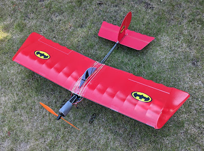
While clearing out recently, I 'found' it. Abandoned for 15 years, covered with dust and rust, it was filthy. The stab had separated from the bent and dented square section alloy fuselage. Steel wire undercarriage and pushrods were rusty, wheels jammed solid, one small tear in the wing, gummed up tape all over the leading and trailing edges and wing centre. For comparison with the refurbed plane above, here is how the standard stick model looks:
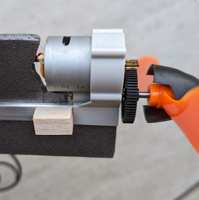
Searching the net for parts (there aren’t many here in the UK!) I saw a new old stock GWS ESC ICS-400Li 25A. This is for brushed motors and LiPO batteries - an unusual piece of electronics! So I decided to start with that, as after all, the geared conventional motor was hardly used. I believe that this is the GWS EPS-300C-D-BB motor, but I’m not certain of that. Perhaps a brushless motor could come later, but how good was the original motor?
A description follows of everything that I did to restore it (where I mention glue, it’s UHU Por unless stated otherwise):
- Using steel wool and 3 in 1 oil, remove rust from wire UC and tail wheel legs. Clean axles with Al-Ox paper, and ensure that the wheels are aligned and rotate smoothly.
- Remove rust from steel pushrods, ensure they move smoothly.
- Clean motor gears and very lightly grease.
- Remove the EP1180 prop, clean, inspect, balance and refit it.
- Straighten alloy stick fuselage. Although it has a dent, I left it as is for now. If we have another urgent visit to Terra Firma, then I'll see about replacing it.
- Remove the German Imperial cross stickers. Remove tape residue from wings, leading and trailing edge carbon rods and their alloy bent tube connectors. “Goo Gone” worked ok. Clean the whole wing, carbon rods and their connectors, stab and fin - microfibre cloth wet with soapy water, another microfibre with clean water, and finally kitchen paper towels to dry. Miraculous colour improvement!
- Mend small tear at the wing centrefold with glue and Tesa white cloth tape.
- Use red Sharpie to colour the bits of the wing where the top shiny red coating had come off.
- Make a large card protractor for: 160 and 170 degrees (dihedral should be within those limits, i.e. 5-10 deg under each wing), and the R E control throws according to the GWS manual (35deg each way and 20-25deg each way respectively).
- Check angle of the alloy tubes and carbon rods with the protractor. They were at around 7deg and within the 5-10deg range. Left them as is.
- Cut a 2mm blue foam canopy profile, to sit between the wing halves. Dry fit together, allowing three 50mm wide spaces at the LE, TE and through a slot in the depron foam. These are to allow tape to be run spanwise in these three places, and for wing rubber bands to cross.
- Glue blue canopy profile and wing halves together with dihedral as per the spars, run tape through the 50mm spaces and slot. Canopy profile was a bit floppy, so I glued on some carbon capping strips that I had lying about to stiffen it a bit and provide detail. Glued on a foam Batman pilot to both sides of the canopy profile.
- File a channel in the LE and TE foam, a cutout for the alloy joining tubes. Glue the carbon spars into the alloy joiners using 5min epoxy. After they set, glue and strategically tape them to the wing LE and TE. See this build info for details.
- Tape chordwise both sides of canopy, through the slot in the canopy, and fore and aft of the canopy, overlapping LE and TE spars.
- Fin seems fairly secure, but not square. Apply a balsa triangle support piece with 5min epoxy, to keep it square and strong.
- Glue a 30 x 1.5 mm balsa mounting plate (grain running spanwise) to stab. Then glue the mounting plate and stab to the alloy fuselage. Mounting plate improves both the joint and rigidity.
- Red Sharpie marker over the balsa plate and touch up the LE of fin. Apply Batman stickers to wings and fin. I think the yellow and black logos look great on the red!
- Fit servos, ensure correct direction and mechanical centre. As I had some handy, used 9g Tower Pro SG92R digital, nylon with carbon fibre gears. These are 4.8V, not rated for 6V, but seem to be ok on a 5V ESC BEC. One was jittery so I replaced it with a good one. I noted that the horns had not been fitted with their pushrod holes directly above the hinge line. "Amateur me", back then! The horns were still fixed securely and the 3M Blenderm hinge tape was in great condition. For stability, add a couple of small fresh pieces of 3M Blenderm tape to the rudder hinge above and below the horn.
- Cut out grey 6mm depron fuselage profile and glue to alloy fuselage stick. Glue small balsa blocks on each side of alloy fuselage, just behind the motor mount. Wrap soft 2mm foam sheet around the nose to form a cowl, using double sided foam tape to fix it to the balsa blocks. It was minimal and basic, just to give the impression of a Fokker Eindecker. Later I swapped this for a darker foam.
- Fit remainder of radio gear, including solder 2mm bullet plugs for motor to ESC, battery, Rx. Set control throws using the protractor. Set failsafe and throttle arm switch. In view of the horn placement, I had to program the throws to ensure the same amount of travel in each direction.
- Balance point was set to 100mm behind the leading edge. My thinking behind this is as follows. The instruction booklet says 105mm for the EPS-300C motor, which is what I think this is, and 95mm for the EPS-400, which was a more powerful unit. Previously, I had been flying this plane with NiMH batteries at 105mm without any issues. So as I’m now using LiPOs, I’ve moved it forward a bit, but not as much as 95mm. Hmm, let’s see how it goes - it’s just a starting point as they say.
- With a 2S 1300 mAh LiPO battery, and balanced at 100mm from LE, it weighs 408g, which is the lower end of the range stated in the instruction manual (405g-440g).


No comments:
Post a Comment