Sunday, January 27, 2008

Vintage "Old Timer" Chuck Glider

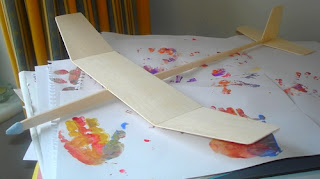
I've finished and flown the Bowers glider (see photo left). It ended up at 30g flying weight, which is not amazingly light, but not heavy either. The main aim was achieved though, which was to improve over the Wallerstein 22" that I built too heavy at 50g (see earlier blog, Wallerstein was the "wing donor").

Flying at dusk in cool, still air, I was getting "still air times" of 36 to 42s. I may be able to improve the launch by moving the decalage closer to 0-0 for a more direct up line, but it's working consistently at the moment so I'll leave it alone. CoG ended up at about 60%.

In the air it looks "retro-fabulous" and floats around flatly. In the park a bloke and his son wanted to know where to get one! I explained it was self-built from a 1930s design, but did give them a closer look, explained how the DT works, and let the son have a little chuck.

I reckon it could fly away, so I fitted a simple DT flap (shown in the other two photos). This type of DT is typically made with aluminium foil from a drinks can, but I find balsa easier to work with and keep flat to the fuselage. The orange paint on the inside is an aid to see the DT operate. I use 3M Blenderm(TM) tape for the hinge, a little "fingernail" from a drinking straw to push the flap out and a balsa triangle stop to keep the flap perpendicular to the fuselage side. The airflow does the rest. There is negligible weight penalty with such a DT as the timer and parts add up to little over 1g and it is all in the nose.

There is a small increase in profile drag of course, but that will mainly affect the high speed launch, which is one of the biggest variables in any case! After testing, the flap was cut down to about 2" in length, which was found to be enough to turn the glide from the left hand circle into a straight line, while just about avoiding a dangerous "lawn dart" dive.

That's one problem with drag flaps - too big and the plane can spiral dive hard to the right and die an ugly death on crash landing. If the flap is too small, it willl not bring the glider down from a thermal and it goes OOS.

Personally, I think it is important that the flap turns the glide into a straight line, not a turn to the right, so that the plane exits the thermal.

It's all in the lap of the thermal gods!

Wednesday, January 23, 2008

Vintage "Old Timer" HLG plans: build pictures

I think this vintage Bowers 20" HLG is going to be quite an eye-catching chuck glider. Here are a couple of build photos.

Left, the wing has been decorated, orange silk applied to the outer break joints as indicated on the plan, and the wing to fuselage joint is glued, aligned and setting.


Right, is a picture earlier in the build. The fuselage has been roughed out, the wing centre joint glued up and drying.

Monday, January 21, 2008

Plans for Vintage HLG or "Old Timer" Chuck Glider

This photo is of a hand launched glider designed in the 1930s by Syd Wallerstein. It qualifies as "Vintage" according to SAM rules. While pretty, the fuselage is heavy pine and so it flies like an overweight hippo. My best flight with it is 55s, which is pretty poor for a 22" span glider. This "fat boy" weighs in at around 50g. The streamer on the nose is an experimental dropping ribbon DT (which actually worked fairly well).

I'm going to re-use the wings on another vintage glider. The chosen design is also from the 1930s and is by Peter Bowers. I guess he is the same aviator who according to Wikipedia went on to work for Boeing and design the Fly Baby homebuilt aeroplane.


I have no idea how the Bowers 20" HLG will fly, but it is an attractive build for various reasons. First, it is the earliest polyhedral HLG that I'm aware of. Second, it seems to be the very early work of Bowers as a young man (possibly while a teenager) before he went on to become such an accomplished pilot and aeroplane designer. Third, the use of silk on the wing joints is interesting and I have a bit of orange silk knocking around.

The tail moment looks a bit short by modern standards and consequently, the tail feathers have a comparatively large area. It should be fun.


Wings of the Wallerstein cut off, reshaped and then sliced into sections, ready for joining into a Bowers wing. One of the advantages of cutting a wing is that you are able to see the aerofoil cross section. In this case, it was clear that more sanding work was required. You may be able to see that I've avoided the high point line.


Sunday, January 20, 2008

Peck Polymers takes over Sting

Last month, Sting Aero, was snapped up by Peck Polymers in the USA. Sting Aero was a business run by Len Surtees in Australia (photo, left). It was acquired by Peck Polymers/A2Z Corp in an impressively quick transaction.

I suspect that Len did not make the decision to sell lightly. Tim G of Peck clarified: "Sting Aero Product will become a product line that we sell through our Peck Polymers online store in addition to selling through other dealers". (When you click on the link above, click on "FF Gliders" on the left to see the range).

Peck Polymers should be a great home for Len's product range, which includes the following superb, successful English designs (and I would say design classics):

- BUTTERFLY, by Mick Page (photo, right)

- 2KAN, by Mark Benns

Both are UK Nationals winners. Butterfly kits started shipping soon after the acquistion and other kits are ready or nearly prepared to be offered for sale. The range also includes Len's STING HLGs (various spans and past Australian Nationals winner) and the more recent SPIN UP range of DLGs, by Mark Benns which are all established winners.

Tom Norell of Peck Polymers has confirmed that they will also take over running the annual
Heave Ho postal contest. This is a popular, informal worldwide competition originally started by Kevin Brown some years ago. Tom also said:

"We here at A2Z Corp./Peck Polymers hope to continue Len's tradition of high quality competition kits and accessories. If you need something that is not listed yet or have any suggestions feel free to email me directly here at the plant. tomn@peck-polymers.com"

Chuck Glider wishes you all the best of luck!

Tuesday, January 15, 2008

Chuck Glider from one 1/16" balsa sheet: Part 4, Trimming

Here are a few views and a video (below) of the finished plane. See Part 5 as well, for further developments.

I think it looks neat, so thanks to the wife for choosing this wing profile!

I've decided to call it PLAIN SAILOR because the build was easy, it seems to have produced a decent performance and exactly as designed.


A view from underneath.

With the balance at 63%, I did some glides from the shoulder. I was pleasantly surprised that it needed no trimming at all. It flew straight and level in a good, floaty glide. No elevator or rudder, washout, washin etc required at all at this stage.

This one flew right off the board!


Here is a video of a test glide from the shoulder. It was blustery 20 mph winds today, but I managed to gently glide it a few times during lulls. Indoors, in the living room, it is very stable and floats serenely with a nice flat glide (I can tell because it hits the curtain high up on the other side of the room). Now I need to find an indoor venue to trim and fly it properly. For example, perhaps the stab or fin could be reduced in area.


If you make PLAIN SAILOR - see the FREE plan in part 5 (Feb 08) of this series of blogposts, and build guide below - please let me know how you get on.


Chuck Glider from one 1/16" balsa sheet: Part 3, Building

I've been building at night and it has been murky and overcast lately, so apologies for the dark pictures. Here we go step-by-step:

Photo 1. After looking at the grain, deciding which side will be the wing and fuselage, make the first cut dividing the sheet into 17" and 19" pieces. (NB. the final version requires an 18" piece for the fuselage, not 19" - see Part 5 of this series of blogs).


Photo 2. Marking out the fuselage. Cut a 22 mm strip from the 19" piece and then mark 4 mm at each edge.


Photo 3. Here are the fuselage sides, fin and stab cut out of the 19" piece. The back of the right hand fuselage side is trimmed to accommodate the fin. See photo 4. When deciding which piece should be which, ensure that any natural bow in each side opposes the other. This helps to prevent a banana fuselage! (But don't worry if you get a bend, as it can be steamed out easily over a boiling kettle).


Photo 4. Note sharper taper over last few mm of fuselage. Glue the fin in place and then the fuselage sides together. Use PVA and spread it out thinly on both faces.


Photo 5. Place a steel ruler and weights over the whole fuselage and fin assembly while PVA dries.


Photo 6. Shaping the wing. First, round off corners and the LE. For the slope, I felt that sanding the top surface from 33% as originally planned may compromise strength. I decided to taper from 50% of chord. Take care with the razor plane! The blue masking tape prevents errors with the sanding block.


Photo 7. Sanding wing break joints. The sanding block face is kept vertical, and the tip is placed as shown to get the right slope. The middle panel joints are sanded while it is flat on the board. With care, it is easy to get a good joint with such a thin wing.


Photo 8. Wing glued up. Middle panel weighted and tips have light weights (balsa off cuts) just to keep it all lined up. I used Araldite Rapid epoxy, spread evenly on both joint surfaces, but thinly.


Photo 9. Here are all the parts ready for assembly. I made a throw tab - it adds strength to the wing-fuselage joint and would be useful for duration tasks. The long thin piece is the nose skid.


Photo 10. Use CA to glue on the skid, and rubber bands to hold it while it dries. Looks like the nose will be quite strong, so I would be able to taper it later for a better appearance.


Photo 11. Thin the stab. You should be able to see translucent light through it near the TE.


Photo 12. Sand the fin thin as well.


Photo 13. All aligned and glued up. Rubber cutting mats are great for this. Use a set square to ensure that everything is square, especially the fin is perpendicular to the stab (while the stab is flat on the mat).


Photo 14. Check tip heights before the glue dries!


Photo 15. Shape the nose. The skid ensures some strength.


Photo 16. Glue and shape the throw tab - note grain direction. Not easy to see at this angle, but the skid overlaps the sharp end of the tab by ~ 5 mm.


Photo 17. Add blue tack to balance at about 1 1/8" in front of the TE, that is about 63%. Total weight came out at 10.4 g.

All done, lovely!

Saturday, January 12, 2008

Chuck Glider from one 1/16" balsa sheet: Part 2, PLAN

As I said, I could not decide on the wing planform. So, I asked my wife to choose one out of D, E, F and K. She went for E. Why? Because it looked the best. Good enough reason for me! I suppose E requires the least amount of work too, which is in keeping with the Design Objectives.

FREE PLAN!

I sketched out a quick plan for the prototype (left). PLEASE NOTE: this is for the prototype - the final plan is in Part 5 of this series of blogs (in Feb 08). You can download by right clicking and then saving. Each square represents an inch.

DESIGN DETAILS

1. All dimensions are inches except for the close-up of the fuselage cut lines, which is in mm.

2. Longish nose for less overall weight. Some indoor gliders have really long noses.


3. Nose skid for hard landings.

4. Wing aerofoil: flat underneath, sand the LE to an elliptical profile, top and bottom parallel for about 33% and then sand a taper on top to as sharp as I dare at the TE. (Most lift force from a wing comes from its angle of attack, not its aerofoil shape. Here, I'm just trying to improve on the "flat plate". Perhaps Prototype 2 will have undercamber...)

5. The TE of wing tips, stab and fin should be really thin so that trim can be "breathed and bent" into the balsa. (This is the typical HLG way to warp flying surfaces for trimming).

6. Build it straight (no stab tilt, wing offset, skew, etc). It should fly straight and level! Turn can be induced with blue-tack on one wingtip, a bit of rudder and wing warping.

7. Laminated fuselage. Two pieces of 1/16" balsa stuck together. The glue must be PVA, because the adhesive line will provide some flexible strenth. Hopefully, it won't weigh too much. The taper in the fuselage, wing on top and stab underneath means that there is some built in decalage, but it is very close to 0-0.

8. Longish moment arm (distance between aerodynamic centres of wing and stab), for stability.

9. Try to keep the back end light. This means sanding down the stab and fin so that they are quite thin, a tapered fuselage with a sharper taper over the last inch or so and using glue sparingly.

10. I have guestimated the amount of polyhedral and the areas of fin and stab.

I'll build her and post photos as I go. I'm hoping that the weight without ballast will be under 14g (ideally, the flying weight with ballast should be under that). That would make the wing loading about:


0.5 / (46 / 144) = 1.6 oz/ft^2


That's lighter than a typical outdoor HLG, but heavier than an indoor duration HLG (which are ridiculously light). Have to think of a name....


Chuck glider from one 1/16" balsa sheet: Part 1, Aims

There is an interesting thread on the Small Flying Arts forum, started by Allan Wright (the designer of the Gambler AG radio control discus launched glider DLG). It is all about designing and making a chuck glider out of one balsa sheet of dimensions 3 x 36 x 1/16". You are allowed to use glue and clay for ballast, but nothing else. The glider is to be flown indoors on various tasks. E.g. longest glide, duration, spot landings, etc.

Very interesting challenge. I thought it would be fun to go through the design process and share it on this blog.

DESIGN OBJECTIVES

I decided that the main aims are:

1. A good glide. So this means maximum span and minimum weight (which is the same as min wing loading and max AR - see earlier blogs on L/D)

2. Stability

3. Trimmable for straight flight AND a turn. This is different to the usual HLG objective, which is a thermalling circle (usually a left turn for a right handed thrower))

4. Reasonably robust (for the spot landing) but not a "tank". This means that the extremely light weight Indoor HLG designs are out of the question

5. Simple design and easy to build - suitable for a beginner

MATERIALS

There is a huge variation in balsa. My 1/16" sheets vary from 9g (very light and flexible) to about 20g (hard and stiff). I'm going to make the first prototype from mid weight stuff. After playing with my sheets and waving them around (which I must admit was fun) , I decided to go for a 17 x 3 inch wing.

PLANFORMS

I did the sketch above on the train while commuting. Squared paper allows you to estimate wing area.
  • Planform A is the whole rectangular sheet: big area, 51 in^2 and AR of 5.7
  • Planform G is sort of elliptical: area is 43 in^2 and AR of 6.7
  • The others are somewhere in between
Planform A would have the most lift and drag, G the least. The shape also affects the strength of the wing, especially at the tips. I have probably decided that the design will be a 3 panel polyhedral (two breaks). This allows easy gluing to the fuselage and since each panel is small, more stiffness and strength. Lighter tips are better.

At the moment, my favourites are D, E, F and K. Hmm....need to think about this....
Google